Index
- 1.0 Introduction
- 2.0 Frame and Legs
- 3.0 Track
- 4.0 Wiring
- 5.0 Control
- 6.0 Scenery
- 7.0 Glossary
- 8.0 Revision History
- File Attachments
Legend
S x.y, where x. and y are number – example: S2.15
RP x.y, where x. and y are numbers – example: RP 5.11
FAQ abx.y, where ab are S or RP, and x. and y are numbers – example FAQ S1.7, FAQ RP3.2
S = Standard. All Free-mo modules and participants must conform to the requirement/standard stated.
RP = Recommended Practice. These are procedures or specifications which are strongly encouraged for maximal reliability or fidelity.
FAQ = Frequently Asked Question/Answers which explain the reasoning behind a particular Standard or Recommended Practice. Free-mo FAQ Page.
1.0 Introduction
S1.1 The objective of the Free-mo Standard is to provide a platform for prototype modeling in a flexible, modular environment. Free-mo modules not only provide track to operate realistic models, but also emphasize realistic, plausible scenery; realistic, reliable track work; and operations. Free-mo was designed to and continues to push the envelope of modular model railroading to new heights. It goes beyond the traditional closed-loop set-up in creating a truly universal “free-form” modular design that is operations oriented and heavily influenced by prototype railroading.
S1.2 Interoperability: The Free-mo Standard is a collection of requirements for building scale model railroad modules that can work together with little effort, even when they have never been assembled together before. The beauty of the Free-mo standard is that it allows builders to replicate any freelance or prototype trackplan within your modules boundaries, yet can be combined for maximal interoperability with other Free-mo modules. (FAQ S1.1)
S1.3 A Free-mo module is a free-form module that conforms to the Free-mo Standard as outlined below. (FAQ S1.3)
S1.3.1A Free-mo module can be any length and the endplates can be at any angle to each other.
S1.3.2A Free-mo module can be one section or a set of two or more sections that form a module.
S1.4 The Free-mo Standard governs the ends of the module and basic track requirements. Most Free-mo modules have two ends, but modules can have one, two, three, or more ends. (FAQ S1.4)
S1.5 Free-mo modules fall into three basic categories:
S1.5.1 Mainline – Mainline modules represent Mainline rights-of-way. Mainline modules are designed with large radius curves and minimal grades.
S1.5.2 Branchline – . Branchline modules represent Branchline rights-of-way. Branchline modules can have smaller radius curves and steeper grades than Mainline modules.See the Free-mo Branchline Supplement for more details.
S1.5.3 Mini-mo – Mini-modules (mini-mos) have endplates that are narrower than the standard width endplate. With this in mind, a mini-mo can be Mainline or Branchline module, single-track or double-track. (FAQ S1.6) See the Free-mo Mini-mo Supplement for more details.
S1.6 Mini-mo type modules are intended to be a Free-mo subset and not replace or exclude an equivalent length standard module. Full width modules are generally more stable and should be used wherever possible.
2.0 Frame and Legs
S2.1 Endplates shall be 3/4″ plywood or equivalent (birch plywood works well) to provide sufficient strength for clamping to adjacent modules. (FAQ S2.1, RP2.1.1)
RP2.1.1 Avoid Dimensional Pine Lumber for your frame work. It has a tendency to warp and “cup” with age, throwing off track alignment. It has also been found that plywood (birch plywood works well) warps and twists less than dimension lumber (3/4 inch pine boards). (FAQ S2.1)
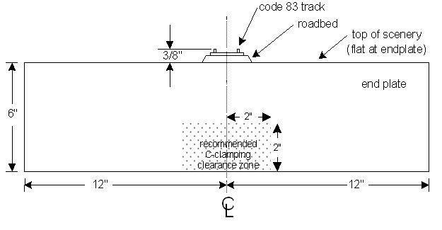
S2.2 Single-track endplates shall be 24 inches wide by 6 inches tall.
S2.3 Double-track endplates shall be 26 inches wide by 6 inches tall.
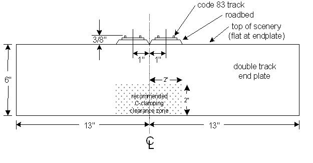
S2.4 Roadbed shall be 1/4 inch cork or equivalent on 1/2 inch plywood or equivalent. Foam tops are acceptable if braced to prevent sagging or flexing.
S2.5 The nominal and minimum height of the railhead, at the end plate, is 50 inches from the floor. (FAQ S2.5)
S2.6 On modules with grades, the elevation of the high end shall be some multiple of 3/4 inch above low end. (FAQ S2.6)
S2.7 The maximum height of railhead , at the end plate, is 62 inches from the floor. (FAQ S2.7)
S2.8 The module (set) shall have at least four legs and stand on its own.
S2.9 Legs shall have continuous adjustment of plus or minus 1 inch (screw type foot).
S2.10 The bottoms of the legs shall have rubber tip or equivalent floor protection.
S2.11 Modules may be used with operators and spectators on either or both sides. (FAQ S2.11)
3.0 Track
S3.1 Modules shall use flex or hand-laid track.
S3.2 The centerline of the all tracks shall be 4 inches or more from the sides of the module at all times. (FAQ S3.2)
S3.3 On a Single-track module, the through track shall be centered on the 24-inch endplate.(see S2.2)
S3.4 On Double-track modules, the two through track centerlines shall be spaced precisely 2 inches apart and centered on the 26-inch endplate.(see S2.3)
S3.5 Track on the through route must be perpendicular to the endplate for 6 inches from each end of the module.
S3.6 Track on the through route must be straight and level for 6 inches from each end of the module.
RP3.6.1 The points of a turnout should not be within 6″ of the end of a module.
S3.7 Rail shall be cut off 1 inch away from module end; ties and ballast shall be continued to the module end for good appearance and matching with the adjacent module. Ties shall be notched under the ends of the rails and to the module end, to clear bridge rail joiners and provide freedom of adjustment for bridge rails. (FAQ S3.7)
RP3.7.1 To enable DCC power districts, your module must be able to accommodate insulated rail joiners at each Free-mo endplate.
RP3.7.2 Free-mo printed circuit board tie plates are recommended for ends. (FAQ RP3.7.2)
RP3.7.3 Tie plates where the fitter rails go over should be excavated slightly to permit fitter rails to accommodate any vertical irregularity in track alignment between adjacent modules.
S3.8 Turnouts shall be at least #6.
RP3.8.1 Turnouts on the module through route should be #8 or larger.
S3.9 There shall be a minimum of 12 inches of straight track between reverse curves.
S3.10 Track on the through route of a Mainline module must ALL be Code 83 nickel-silver rail without exception.
S3.11 Sidings, spurs and other tracks of a Mainline module may be Code 83 or smaller, but shall be no less than Code 40.
S3.12 The minimum permitted curve radius on a through route of a Mainline Module is 42 inches. This includes through track sidings and other tracks where through traffic will run.
RP3.12.1 While the minimum permitted radius of curves on the through route of a Mainline module is 42 inches, 48 inch and larger curves are preferred.
S3.13 Spacing between tracks on curves of a Mainline module shall allow for long cars to operate without fouling each other; observe NMRA Standards RP-7.2 Track Centers for “Early Modern and Modern” equipment.
S3.14 Mainline maximum permitted grade on the through route of a Mainline module is 2.0 percent (approximately 1/4 inch per foot).(FAQ S3.14)
S3.15 Curves on the through route of a Mainline module shall be appropriate for Mainline operation of Modern Equipment see RP-7 Track Centers and Obstacle Clearances (NMRA RP-7.2 Track Centers and Obstacle Clearances) and NMRA TN-2 – Standards Gauges.
4.0 Wiring
S4.1 Wiring consists of 2 pairs of bus wires (Track Bus and Accessory Bus), a 6-conductor LocoNet bus cable and a single wire Booster Common.
RP4.1 The length of the free ends of the Track Bus , Accessory Bus and the Booster Common at each end plate shall be a minimum of 18 inches.
S4.2 Track and Accessory Bus wire shall be 14 AWG stranded or larger wire.
S4.2.1 Modules in existence prior to 1 July 2015 may have track and Accessory Bus wire that is 18 AWG. It is highly recommended that they are upgraded to 14 AWG stranded or larger wire.
S4.3 The LocoNet bus shall be telephone type 6-conductor cable.
RP4.3 Digitrax advises against using Computer CAT type cable. The LocoNet bus should be telephone grade flat cable, not computer twisted pair Ethernet cable.
S4.4 There shall be a 4 (or more) position barrier strip under the module at each end for track and Accessory Bus wire hook-up.
S4.5 The Track Bus shall be terminated on all ends with a pair of Anderson Powerpole PP15-45 Standard Housing incorporating a 30 amp power contact for use with 12-14 gauge wire. The PP15-45 connectors shall be stacked vertically (hood up, tongue down).
While facing the module from the end with the hood of the stacked connectors up:
- The top PP15-45 shall connect to the left rail.
- The bottom PP15-45 shall connect to the right rail.

RP S4.5 Obsolete, removed.
S4.5.1 Obsolete, removed
S4.6 The Accessory Bus shall be terminated on all ends with a pair of Anderson Powerpole PP15-45 Standard Housing connectors incorporating a 30 amp contact for use with 12-14 gauge wire. The PP15-45 connectors shall be stacked horizontally (tongue-to-tongue, hood-to-hood). (See figure in S4.5)
RP S4.6 Obsolete, removed.
S4.6.1 Obsolete and removed.
S4.7 All ends shall have a surface mount “6 conductor 6 position” module jack (RJ12) mounted to the inside of the endplate for the LocoNet Bus. .
S4.8 Through route track wiring.
S4.8.1 Obsolete, removed.
S4.8.2 Obsolete, removed
RP4.8.1 – On double track modules, to facilitate optional train signaling/detection, separate feeders are recommended for each track so that detection can discern a train on track A or track B.
S4.9 Track feeder wire must be 24 AWG or larger, but not longer than six inches to the Track Bus to avoid voltage loss.
S4.10 All turnout frogs shall be powered. Turnouts shall not rely on switch points to power the frog.
S4.11 Accessory power shall be approximately 16 volts AC or DCC. The bus is wired straight through. A bridge rectifier and filtering capacitor may be used to convert AC or DCC signal to DC. Applications that require AC or DCC signal may utilize power directly from the bus. (FAQ S4.11)
S4.12 Each module will have one dual flush mount “6 conductor 6 position” modular jack (RJ12) faceplate mounted on each exposed side of module, for throttles. (Digitrax UP-5 Throttle Jack or equivalent)
RP4.12.1 For maximal convenience in areas where operators congregate (such as yard modules) one or more modules in these areas should have more than one set of throttle jacks per side.
RP4.12.2 On Multi-Section Module, each module sections should have a dual flush mount “6 conductor 6 position” modular jack (RJ12) faceplate mounted on each exposed side.
S4.13 All of the LocoNet connectors and associated cables need to be connected together straight through (i.e. pin 1 – pin 1, pin 2 – pin 2, pin 3 – pin 3, etc. …note standard telephone cables are NOT wired straight through).
S4.14 To connect the DCC bus between modules, a 2-foot RJ12 to RJ12 type straight through cable is utilized.
S4.15 To connect a DCC booster to a module, There are two connections that have to be made. (1) The LocoNet (2) The Track Power.
S4.15.1 For the LocoNet, a 4 foot RJ12 to RJ12 type straight through cable is utilized.
S4.15.2 Obsolete, removed
S4.16 All modules shall incorporate one wire for a Booster Common that is 14 AWG stranded or larger.
S4.17 Booster Common shall be terminated on all ends with an Anderson Powerpole PP15-45 Standard Housing connectors incorporating a 30 amp contact for use with 12-14 gauge wire.
S4.18 The Anderson Powerpole PP15-45 connectors for the Track Bus, Accessory Bus, and the Booster Common shall be three separate sets of connectors.
5.0 Control
S5.1 LocoNet compliant DCC and accessories are standard for interoperability within and between Free-mo groups. For more information about LocoNet Technical specifications consult the Digitrax website.
S5.2 For a given turnout, turnout controls must be on all sides of the module or module section, excepting any endplates.
RP5.2.1 Turnout controls should be located on the fascia, and not on the horizontal or vertical surfaces of your scenery.
6.0 Scenery
S6.1 All benchwork shall be hidden by some form of scenery.
S6.2 General module fascia color shall complement scenery and not draw attention from the scene.
S6.3 Scenery at the Free-mo standard end(s) shall have a flat profile 3/8″ below the top of the rail on the through route.
S6.4 The through route shall be ballasted Woodland Scenics Fine Light Gray or equivalent,
S6.5 Standard rail color on the through route is Floquil/Polly-S Roof Brown or equivalent.
RP6.5.1 Ballast on Through route is to be weathered with a fine mist of thinned Floquil/Polly-S grimy black or equivalent.
7.0 Glossary
- Anderson Powerpole Connector – refers to the PP15-45 Standard Housing incorporating a 30 amp contact for use with 12-14 gauge wire. http://www.powerwerx.com/techdata/PP30.pdf, http://www.andersonpower.com/files.php?file=DS-PP1545(25).pdf
One source for the Anderson Powerpole connectors referenced throughout this standard is:
http://www.powerwerx.com/anderson-powerpoles/powerpole-sets/
http://www.powerwerx.com/anderson-powerpoles/housings-contacts/ - Booster Common
- Branchline Module –
- Mainline Module –
- Mini Mo –
- Through Route –
8.0 Revision History
Free-mo Standards & Recommended Practices Revision History
2024-03-25 Removed references to Cinch Jones Connectors
2023-10-11 Updated NMRA links in 3.13 and 3.15
2015-09-20 Added link to Branchline standards.
2015-06-14 Added Anderson Powerpole connectors to the standards. Updated AWG wire size.
2015-03-03 Added links for FAQs
2014-02-18 Updated the Cinch Jones part number in S4.5
2015-02-16 Updated FAQ Numbering. Created FAQ page.
2014-12-22 Added RP4.3
2014-02-01 Typo in S3.15. It said “Vertical curves on …” changed to “Curvers on …”
2013-12-28 Fixed numbering error, S4.1.15.1 and S4.1.15.2 should have been S4.15.1 and S4.15.2
2013-12-12
Replaced “buss” with “bus”.
2010-09-11
Section S4.8.4 Double Track, changed “rail” to “rails” in 4 places. Ex: “Male contact 2 right rails” to make the standard more clear.
2008-03-16
Updated the links out to the NMRA site to the new NMRA site.
Changed a comma to a semicolon in S1.1 “…emphasize realistic, plausible scenery; realistic, reliable trackwork; and operations.”